Dec 18, 2023Use a daisy chain topology. The DMX standard specifies that a network of DMX devices can only be connected in a simple linear, daisy-chain configuration, as shown in Figure 1. Never extend a DMX network via T-taps or Y-taps: when connected in anything other than a daisy-chain topology, DMX luminaires are susceptible to signal distortion or failure.
DMX/RDM Guide – Insight Lighting
Notice at collection. . Oct 15, 2019 – XLR Wiring Diagrams and Standards, for 3 & 5 Pin XLR Connectors. Details on polarity, colour coding and wiring standards. DMX & Audio.

Source Image: pinterest.com
Download Image
Sep 1, 2022Sep 01, 2022 For beginners in stage lighting, one of the ideas that can be baffling is how to wire up all of your fixtures. Back in the “old days” you simply ran control cable to your dimmers, and power out to your conventional fixtures. It was pretty simple overall, with no “settings” or configuration required on your lights.

Source Image: pinterest.com
Download Image
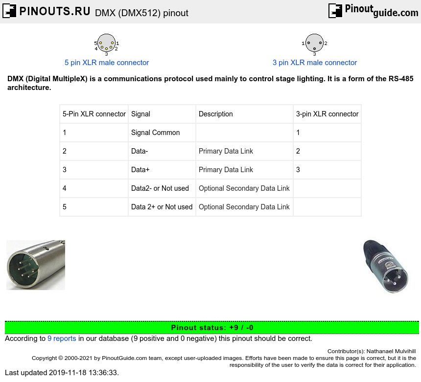
DMX (DMX512) pinout diagram @ pinoutguide.com Here’s a summary of best practices we recommend for how to wire DMX lighting systems: Use twisted pair cables with an impedance of 120Ω and a low capacitance. UTP Cat5 or Cat6 network cable is another option but it has a slightly lower impedance of 100Ω. Terminate at the last driver with an impedance of 120Ω.

Source Image: wired4signsusa.com
Download Image
Dmx Wiring Diagram
Here’s a summary of best practices we recommend for how to wire DMX lighting systems: Use twisted pair cables with an impedance of 120Ω and a low capacitance. UTP Cat5 or Cat6 network cable is another option but it has a slightly lower impedance of 100Ω. Terminate at the last driver with an impedance of 120Ω. DMX Pinouts and Wiring With the right DMX cable at your disposal, there are a plethora of ways to make the connection ( CueServer supports up to 7 different standard connection types alone!) . Take a look below for pinouts for the most popular connectors. 5-pin XLR Pinout DMX 512 Standard
Wireless DMX Controllers for Sale ☑️ Best Prices Guaranteed
16 mars 2018 Dmx To Rj45 Wiring Diagram. Dmx. Discover Your Wiring Diagram … 16 mars 2018 – Dmx To Rj45 Wiring Diagram. Dmx. Discover Your Wiring Diagram … Pinterest. Explore. When the auto-complete results are available, use the up and down arrows to review and Enter to select. Touch device users can explore by touch or with swipe gestures. Showgear DS-24M/3 DMX Rack Split 8x 3-pin male XLR to 2x female RJ45 C – Simply Sound and Lighting

Source Image: simplysoundandlighting.co.uk
Download Image
DMX512 0-10V 3A 1channel Controller – China LED Dimmer, DMX 512 Decoder | Made-in-China.com 16 mars 2018 Dmx To Rj45 Wiring Diagram. Dmx. Discover Your Wiring Diagram … 16 mars 2018 – Dmx To Rj45 Wiring Diagram. Dmx. Discover Your Wiring Diagram … Pinterest. Explore. When the auto-complete results are available, use the up and down arrows to review and Enter to select. Touch device users can explore by touch or with swipe gestures.

Source Image: yawaled.en.made-in-china.com
Download Image
DMX/RDM Guide – Insight Lighting Dec 18, 2023Use a daisy chain topology. The DMX standard specifies that a network of DMX devices can only be connected in a simple linear, daisy-chain configuration, as shown in Figure 1. Never extend a DMX network via T-taps or Y-taps: when connected in anything other than a daisy-chain topology, DMX luminaires are susceptible to signal distortion or failure.

Source Image: insightlighting.com
Download Image
DMX (DMX512) pinout diagram @ pinoutguide.com Sep 1, 2022Sep 01, 2022 For beginners in stage lighting, one of the ideas that can be baffling is how to wire up all of your fixtures. Back in the “old days” you simply ran control cable to your dimmers, and power out to your conventional fixtures. It was pretty simple overall, with no “settings” or configuration required on your lights.
Source Image: pinoutguide.com
Download Image
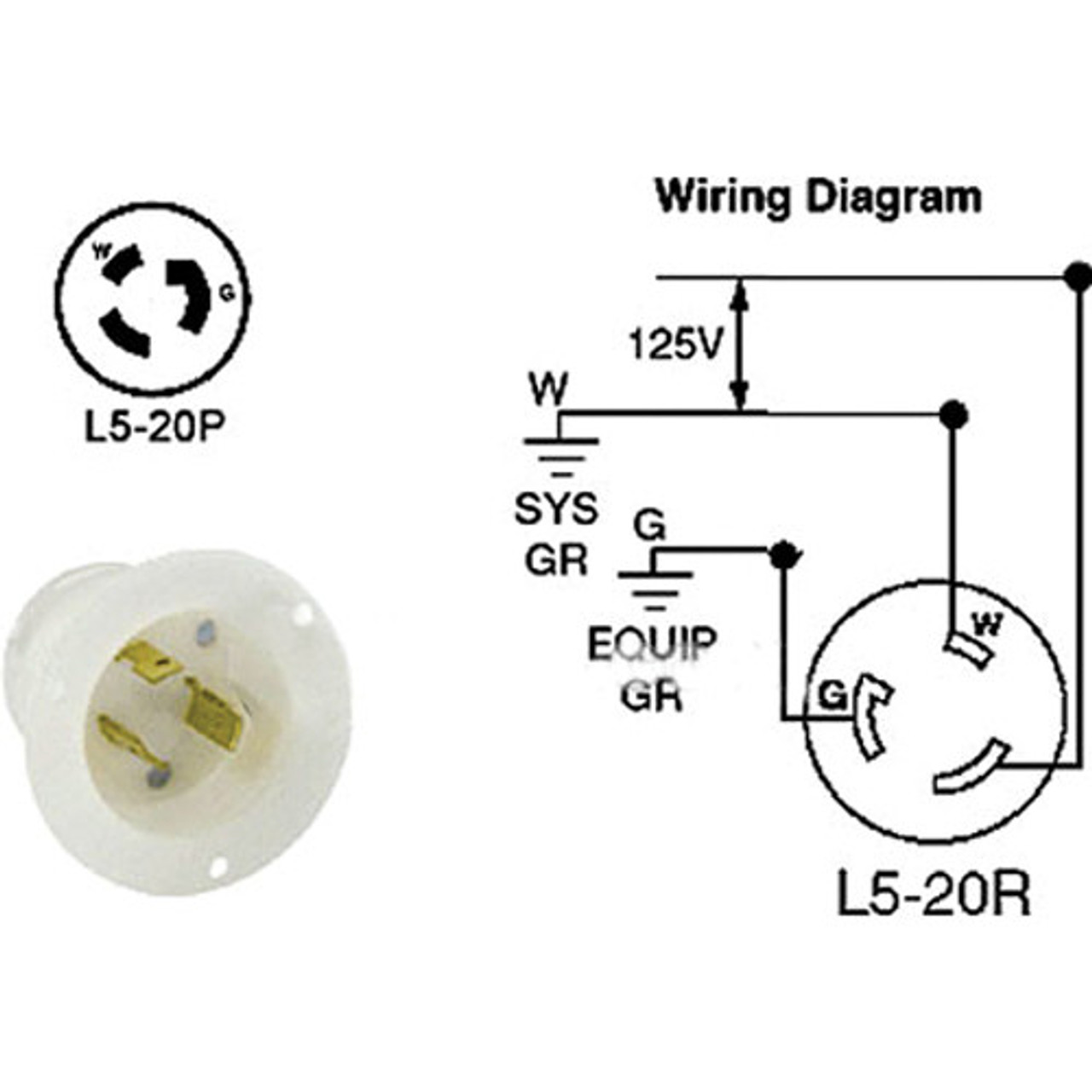
Altman 52-2315 Twist-Lock (L5-20P) Recessed Connector, Male – 20 Amps – GoKnight 1 Connecting the cable on eldoLED drivers with ‘DMX in’ terminals only Drivers with only one set of DMX terminals (DMX in +, DMX in -, and DMX in shield) use a standard DMX bus topology (daisy chain). At the last driver, a 120Ω resistor must be connected between the DMX in + and DMX in – pins of the driver as termination.
Source Image: goknight.com
Download Image
DMX Touch Panel RGB/RGBW LED Master Controller HUEDA LW-2812WI – LED World Lighting Here’s a summary of best practices we recommend for how to wire DMX lighting systems: Use twisted pair cables with an impedance of 120Ω and a low capacitance. UTP Cat5 or Cat6 network cable is another option but it has a slightly lower impedance of 100Ω. Terminate at the last driver with an impedance of 120Ω.

Source Image: ledworldlighting.com
Download Image
Beautiful Wiring Diagram Motor Starter #diagrams #digramssample #diagramimages #wiringdiagramsample #wiringdiagram Check more at https://nostoc.co/wiring-diagra… DMX Pinouts and Wiring With the right DMX cable at your disposal, there are a plethora of ways to make the connection ( CueServer supports up to 7 different standard connection types alone!) . Take a look below for pinouts for the most popular connectors. 5-pin XLR Pinout DMX 512 Standard

Source Image: pinterest.com
Download Image
DMX512 0-10V 3A 1channel Controller – China LED Dimmer, DMX 512 Decoder | Made-in-China.com
Beautiful Wiring Diagram Motor Starter #diagrams #digramssample #diagramimages #wiringdiagramsample #wiringdiagram Check more at https://nostoc.co/wiring-diagra… Notice at collection. . Oct 15, 2019 – XLR Wiring Diagrams and Standards, for 3 & 5 Pin XLR Connectors. Details on polarity, colour coding and wiring standards. DMX & Audio.
DMX (DMX512) pinout diagram @ pinoutguide.com DMX Touch Panel RGB/RGBW LED Master Controller HUEDA LW-2812WI – LED World Lighting 1 Connecting the cable on eldoLED drivers with ‘DMX in’ terminals only Drivers with only one set of DMX terminals (DMX in +, DMX in -, and DMX in shield) use a standard DMX bus topology (daisy chain). At the last driver, a 120Ω resistor must be connected between the DMX in + and DMX in – pins of the driver as termination.

